Background
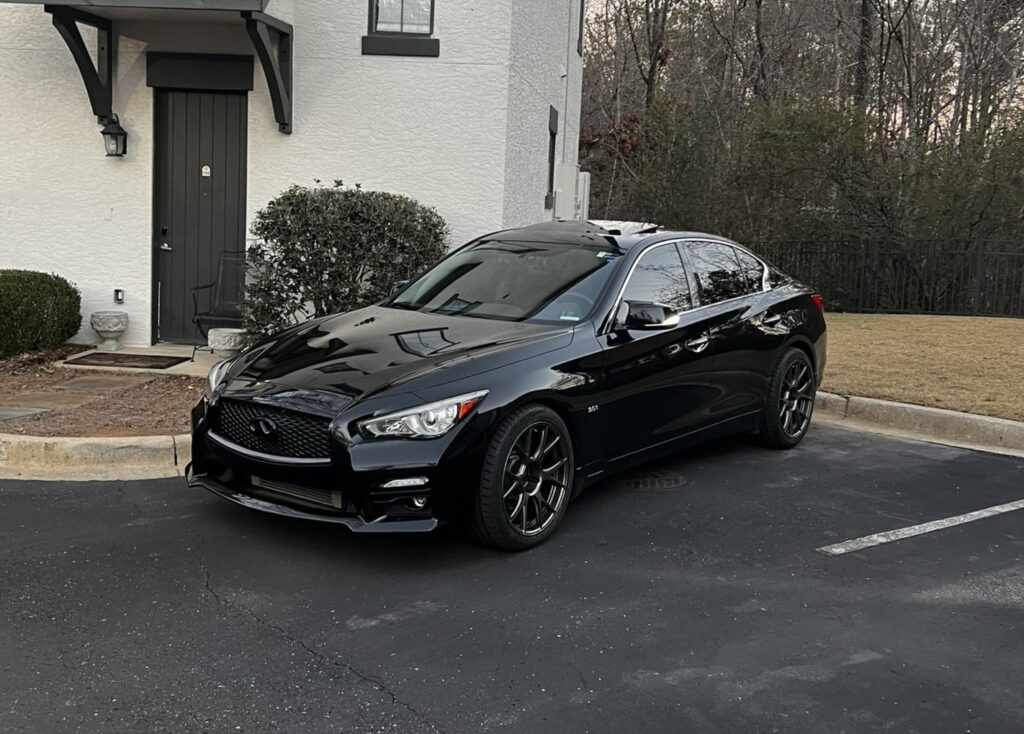
My 2016 Infiniti Q50 is my pride and joy. It’s my second Q50, 3rd Infiniti, and 4th Nissan vehicle for a reason. I believe the Q50/Q60 remain one of the sleekest cars on the road, and I know firsthand what the VR30 powertrain is capable of. Working as a software + embedded engineer for 3 years, I naturally got bored enough to start poking around my Q. This blog post details the results of reverse engineering and playing around with the infotainment system, the CAN bus, the gauge cluster, and building a custom telematics control unit on board my car.
The CAN Networks
For the past couple of years, my job has involved development, implementation, and reverse engineering of CAN 2.0 based networks. Because of this, I figured the perfect place to start was by sniffing the CAN networks on board the car to see what I could find.
There are two CAN networks on my car (I don’t have the fancy driver assist features that give you multiple non-AV CAN busses behind a gateway). In the FSM they are referred to as CAN and AV-Comm, however I call them vCAN (vehicle CAN) and avCAN for short.
Vehicle CAN
First up was the vehicle CAN bus. I really just wanted to see what all I could find. When reverse engineering a CAN bus, the best place to start is with the gauge cluster. This is for two reasons:
- You can selectively replay certain messages to see visually how things react instantly, plus you can manipulate the messages to identify the byte/bit positions of the identified behavior
- Because I wanted to make it work with a video game, and it is totally awesome.
I was anxious to get things rolling, so I knocked out a quick CAN DBC in a few hours using recorded CAN data from my car to identify the major CAN messages and bit/byte values that the cluster cares about. From there, I wrote some C# code to generate these CAN messages given the desired parameters, plus some glue code to make it read data from BeamNG.Drive and output the generated CAN messages to my PeakCAN-USB.
General Takeaways & Notes
I really like how the Nisan CAN messages are laid out. Minimal multiplexing, minimal reliance on hardcoded values or logic on the gauge cluster (vehicle interoperability), and counters to verify message health.
A couple of notes:
- Nissan does NOT normally make the cluster automatically buzzer beep when there is an alert (ex: car shut off in gear). Instead, the module responsible (ex: TCM/CCM/BCM) for the alert commands the alert as well as a separate buzzer command.
- Some optionally equipped modules (like AWD & DAS) have to be detected once before a module failure to communicate error will occur. Once detected, the cluster must lose power to reset this memory.
- Funny enough, there are 2 bits the BCM can output which will show the trunk open. My guess is other vehicle models use the second bit for trunk status. (Truck tailgates? Nissan models?)
- The cluster only supports up to 8th gear. I still want to put a 9AT from the new Z on my car though.
Message Breakdown
To be clear: this is not an extensive breakdown, it was just what I found to get the cluster working with a game. I didn’t dig much deeper. I also omitted some unneccesary modules/messages.
AWD
ID: 0x1A5
Just a status message with commanded/actual tq. split as well as a counter and faults (OVERHEAT/TIRE_SIZE/ERROR). If you’re making this work with a game, just don’t broadcast it and the cluster won’t throw an FTC error.
CCM – Chassis Control Module
ID: 0x56C
- Byte 0:
- Bit 1: Status, with 1 being CCM error
- Byte 1:
- Bit 1: Command Cluster Urgent Beep
- Bit 2: Command Cluster Intermittent Urgent Beep
- Bits 3-5: Drive Mode
- Byte 5: Counter
BCM – Body Control Module
ID: 0x60D
- Byte 0:
- Bit 2: Headlights
- Bit 3: Driver Door
- Bit 4: Passenger Door
- Bit 5: Rear Driver Door
- Bit 6: Rear Passenger Door
- Bit 7: Trunk
- Byte 1:
- Bit 0: Fog Lights
- Bit 3: High beams
- Bit 5: Left Blinker
- Bit 6: Right Blinker
ID: 0x351
- Byte 5: Cluster Message & Beep Request
- NOTE: For the sake of simplicity, I am going to list the byte values for each message, and then the bit modifiers at the end for beep request. They are the same byte. I also copy and pasted names from the code I wrote out of laziness.
- 0x01: BRAKE_PUSH_TO_START
- 0x03: KEY_ID_INCORRECT
- 0x04: WHEEL_PUSH_TO_START
- 0x05: SHIFT_TO_PARK
- 0x06: POWER_TURNED_OFF_TO_SAVE_BATTERY
- 0x07: KEY_BATTERY_LOW
- 0x08: NO_KEY_DETECTED
- 0x09: POWER_WILL_TURN_OFF_TO_SAVE_BATTERY
- 0x0A: PUSH_IGNITION_TO_OFF
- 0x0B: CLUTCH_PUSH_TO_START
- 0x0E: HOLD_KEY_CLOSE_ANIMATION
- 0x40: KEY_SYSTEM_ERROR
- Beep Modifiers
- Bit 4: Urgent Beep
- Bit 5: Regular Beep
- Byte 6:
- Bit 4: Auto headlights indicator
- Bit 7: Door Open Chime
ID: 0x358
- Byte 3:
- Bit 0: Trunk 2 (that one I mentioned in notes above)
- Byte 4:
- Bit 3: TPMS Light
TCM – Transmission Control Module
- Byte 0: Gear & Status
- NOTE: MTx is manual trans, Mx is auto trans in manual mode
- NOTE 2: The status bit is at the end again. Just like the BCM. I’m lazy here.
- 0x00: NONE
- 0x08: P
- 0x10: R
- 0x18: N
- 0x20: D
- 0x28: D_SPORT
- 0x30: L
- 0x40: MT1
- 0x48: MT2
- 0x50: MT3
- 0x58: MT4
- 0x60: MT5
- 0x68: MT6
- 0x80: M1
- 0x88: M2
- 0x90: M3
- 0x98: M4
- 0xA0: M5
- 0xA8: M6
- 0xB0: M7
- 0xB8: M8
- Status Bit
- Bit 0: AT Error
- Byte 1:
- Bit 2: Shift Denial (flashes gear)
- Byte 2:
- Bit 6: Cluster Beep (for shift denial)
ECM – Engine Control Module
ID: 0x551
- Byte 0:
- Coolant Temp Needle Position
- NOTE: This one is cool. The cluster doesn’t use temp to show the coolant gauge. The ECM commands from 0x00 to 0xFA for the coolant temp needle position. This allows various engines that operate in different temp ranges to use the same cluster code, as well as all logic to lie on the ECM for firmware updates and hysteresis logic. Also lets me turn it into a boost gauge.
- Byte 3:
- Bit 5: Check Engine Light (the bit that has ruined many days)
ID: 0x3EC
- Byte 0: RPM MSB
ABS – Antilock Braking System
ID: 0x284
The ABS system outputs individual wheel speeds here, but the cluster just uses the highest. I just threw it on one of them for the purposes of the video game demo.
- Byte 0: Speed MSB
HVAC
ID: 0x54C
- Byte 0:
- Outside Temperature in C
- NOTE: The cluster filters this value based on speed. That one confused me for a bit.
- 0x00: Invalid (displays as –)
- Outside Temperature in C
AV CAN
The AV CAN system isn’t very interesting. I also lost my notes on it (thanks, OneNote). But it’s essentially this:
- Integral Switch broadcasts integrated + multifunction switch button touch/hold status
- Integral switch broadcasts lower display touch information
- AV system + combination meter communicate for general configuration
- AV system + combination meter use ISO-TP for nav/audio/SMS string transfer
- BOSE amp stuff
Infiniti InTouch
This is where things get interesting. My Q50 came equipped with last-gen Infiniti InTouch. It’s not bad, but in 2021 it left some things to be desired. Namely, I wanted CarPlay and the ability to view my performance gauges on the screen. I started this whole part of the project by
Reverse Engineering Overview: 2014-2019 InTouch
Understanding the system
I wanted to start by getting a general understanding of the system. The FSM was VERY helpful (I love Nissan FSM documentation), but I wanted to dive a bit deeper. I documented this on the forums in the early days of working with the system.
Obtaining Shell Access
I knew it wouldn’t be as easy as the Tzumi MagicTV I played with back in high school, but I knew there were a few attack vectors. However, without an update USB or some wireless access, I had to take another approach.
After taking apart the DCU, I noticed a microSD card. After putting it into my computer, I spotted a boot partition. BINGO! I got a Linux machine spun up and started poking around.
I wasn’t able to do much, because the software was based on Meego, a now dead Linux distribution spearheaded by Intel. This meant I could not get any of the packages or kernel modules I needed to get some fairly modern software running.
To get root, I simply added the following to a shell script that is run at boot that initialized a console instance on a USB device. This allowed me to connect to the DCU via USB with root access.
/sbin/agetty --autologin root -L 115200 ttyUSB0 vt100Poking around the system
I won’t go too in depth since I didn’t go down this route and my documentation isn’t great.
- The first thing I noticed was that there appeared to be traces of Android on this Meego based system (seemed to be named logan). I pretty quickly discovered that InTouch runs a kind of “hybrid OS” model, where an Android subsystem can be utilized for certain apps. I suspect this was so they could have that “app ecosystem” they were dreaming up a while back.
- I believe it used /dev/shm for memory sharing between the two systems
- When you see “loading apps” at startup, the menu is running on the main infotainment software, but once the Android subsystem is loaded – it seamlessly switches to an Android launcher.
- The system is based on GENIVI standards, however I wasn’t able to get too far with publicly available resources. I do believe they are using the GENIVI standards for Wayland compositor as well as Connman for connection management.
- There are interesting users on board such as ivilinux, logan, and the android users I never got to play with.
- The USB-Telematics driver was referred to as cdc_tcu. I wanted to get further into this since it seemed to be a network/tel layer as well as communications layer but my TCU was shut off. :/
Giving Up
I decided to change course after a while because I realized that without proper tooling, I would be fighting a long uphill battle for getting custom apps to work on older hardware. However, I spotted a new project: the new InTouch.
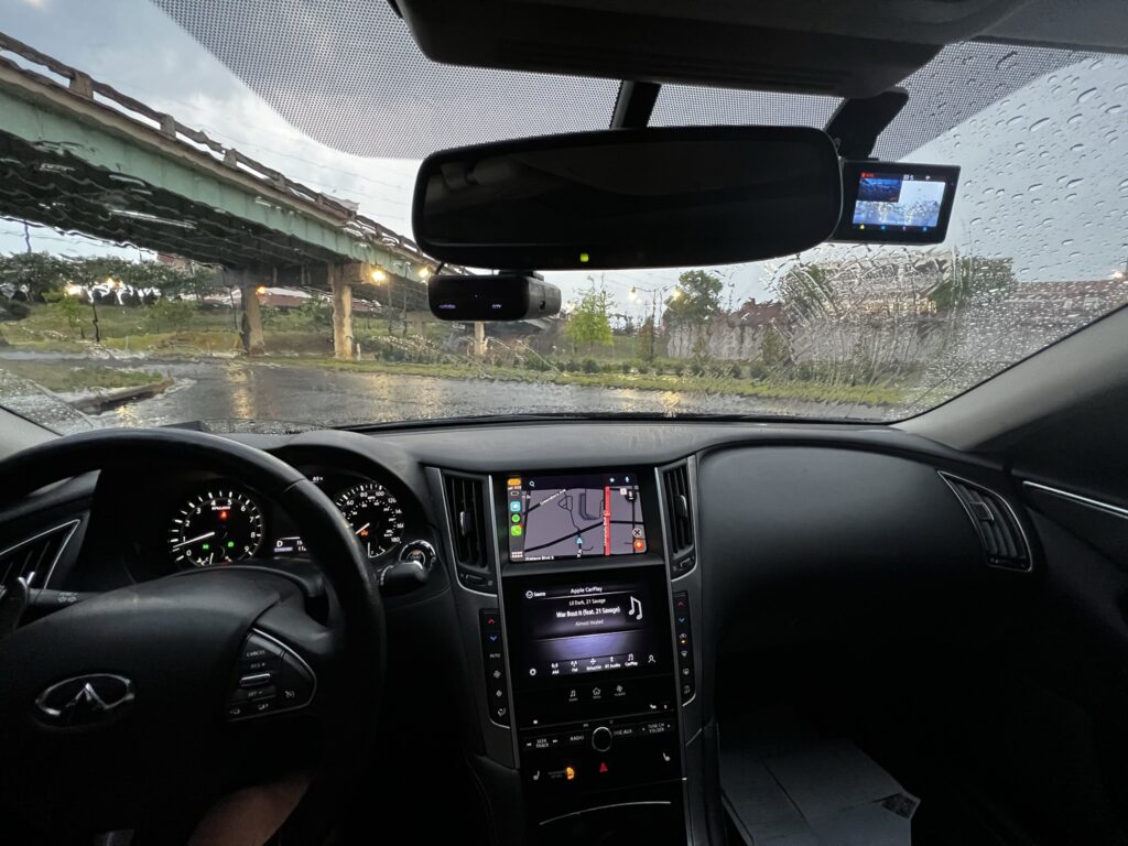
Porting the new 2020+ InTouch radio into my 2016
When I got a loaner during my turbo replacement, I noticed that 2020+ InTouch was COMPLETELY overhauled. It was snappy, responsive, attractive, and modern. The nav was better than Google Maps (my opinion), wireless CarPlay was standard, and it doubled the display quality. I decided I was going to put it into my car.
Connectors: Square in a Circle Hole
The first issue I encountered was looking at eBay listings. The old system was an amalgamation of various modules with a hell of a harness while the new system is streamlined down to the telematics module, the AV control unit (CD player, now it’s the brains), integral switch, and top screen.
After buying the FSM, I realized I could make a simple adapter harness to get the old system on the new harness, and got to work. I bought male to female connector harnesses on AliExpress and repinned them as needed.
Making it all work
The install was pretty painless, and most functions on the car worked, however a few functions were inoperable, all involving the AV CAN bus.
- CarPlay Song Information on Cluster
- Cluster Configuration
- BOSE # audio steps
It was at this point I realized I would need a microcontroller on the car to adapt these avCAN signals. But I can do a LOT with a microcontroller.
Building my own TCU
So, one part I have not touched on is the Telematics Control Unit (not to be confused with the TCM). The TCU is a cool little cellular module that does the following:
- Provides data connectivity to InTouch
- Manages the SOS button + crash functionality
- Sends a crash report in the case of an accident
- Controls power to the InTouch system, keeps radio on during SOS call
- Provides remote key functionality
However, my TCU was shut down during the great 3G shutdown, and TCUs are one time programmable according to the FSM. Plus, I don’t think I could even get my VIN added to Nissan’s cloud portal as it’s a 2016 VIN. So, I made my own.
My Hardware
My hardware choice was pretty straightforward. I built an ESP32 based module that replaced the TCU on board the vehicle. The ESP32 has excellent sleep functionality, and I can use a LILYGO module in the future to integrate a small cellular 4G board.
As for peripherals, all I do with the TCU is the following:
- ESP Built-in CAN:
- Vehicle CAN: the rest of the vehicle CAN network
- MCP SPI Transceiver + Controllers
- AV CAN (to vehicle)
- AV CAN (terminated, to radio)
- IO:
- 12v Radio Power Output
- SOS Button LED Output
- SOS Button SW Input
What mine does
My TCU solves a few quality of life issues I had with the factory one.
- Remote key functionality
- After the 3G shutdown, I lost remote key fob functionality. Through the magic of testing, I have reverse engineered the CAN sleep-ready/wake-up messages as well as the TCU status message. I got each command working, and once I integrate a cellular module I will be able to replicate these BCM command messages remotely and regain remote start/stop/lock/unlock etc.
- The radio shuts off later
- One thing I dislike on the Q is that the radio shuts off when you turn off the car. Sometimes I want to finish a song in my driveway without a twin-turbo Japanese monster V6 drinking my gas.
- To fix this, I now monitor the IGN and door ajar statuses. The radio power output will stay on for up to 5 minutes, until a door is opened., or until voltage drops below a threshold. The bottom screen shuts off but I don’t care.
- SOS button (fun)ctionality
- I remapped the SOS button to send a map change command to my ECM which switches my EcuTek map into high boost.
- The LED indicator uses the map mode PID and is kept on for high boost and off for low boost.
- Logging
- It is so much easier to log with an ESP32 via Wi-Fi than with a PeakCAN-USB poking out from under your leg. I added a GVRET subsystem.
- AV-CAN Patches
- I intercept and modify the messages needed to make the new system work with the old BOSE amp and Combination Meter. I essentially just double the steps broadcast by the BOSE amp and fix the meter page config messages.
- Basic EcuTek integration
- I can detect if the ECM is flashed with EcuTek
- If so, I can read boost/map mode and change maps. There’s a lot more but I need time to sit down and figure out how the aftermarket EcuTek values are scaled/offset + their PIDs.
Upgrading to the 2020+ cluster
Although my AV CAN patch worked, I wanted to update to the new blacked out styling of the 2018_ clusters, and get the digital speedometer. To do this, I used the cluster I bought for the gaming demo. However, the vehicle odometer is baked into the cluster, and I did not want to fool around with odometer fraud.
To work around this, I came up with a nifty solution. I took the odometer reading from my old cluster, and wrote a version of my game code that outputted 170 mph until the odometer reading matched or was greater than my actual. After a quick 5 mile test run, I left it running while I left the country. When I came back, it still had a day left. In total, it took nearly 17 days to correct the mileage.
Once I installed the identical mileage cluster, I disabled the meter avCAN patching functionality of my custom TCU and took the Q on a much needed drive.
Building an Autoshift Module
One issue you run into in the Q tuning world is TCM tuning. No shop has made TCM tuning available for the impressive-already 7AT on the Q50. Because of this, shift points can not be dialed in to the ideal rpms for the modified power band of a tuned vehicle.
As a proof of concept, I designed a simple module that sits between the cluster and extends it’s functionality, including adding autoshift.
How it works
Manual mode upshift and downshift signals are transmitted via bits on the main CAN bus once the line is pulled down by the paddle and read by the combination meter.
- I identified these bits and created a simple program that allows you to set shift points by gear and it will execute the shifts at these points.
- To do this, I have two CAN interfaces. One is to the vehicle, the other is terminated and goes to the cluster. I pass everything through, but intercept and modify messages/bit flags when needed.
- This allows for the more aggressive rpm ranges and shift points of manual mode, without the need for a TCM tune.
- It only activates when enabled and in manual mode, however when off it beeps in manual mode as a shift indicator (using the TCM shift denial beep message) right before the point where it would trigger an upshift if enabled.
- I also added functionality to turn the coolant gauge into a boost gauge.
Please ignore the electrical tape mounting and crimp connector wiring. I have plans to move this to an STM32 in-harness module and hide it behind the cluster. The display was more for diag purposes, and is slow to update.
More to come?
While I am very happy with my car as it is, I see more opportunities for the future. Once I have my current projects polished, I plan on attempting a fully digital cluster project that integrates all OEM functionality as well as aftermarket EcuTek functionality.